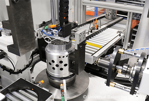
To the average person, rotor balancing is often a “black art”. Most people’s knowledge of balancing is limited to car wheels and tyres that must be balanced before fitting to cars; otherwise they will experience steering wheel judder, uneven wear on tyres and so on. We’ll help give you insight into the world of balancing and help to remove the “black art”.
AN UNBALANCED ROTOR
Unbalance exists in a rotor when the mass centre axis is different to its running centre axis. Practically all newly machined parts are non symmetrical due to blow holes in castings, uneven number and position of bolt holes, parts fitted off-centre, machined diameters eccentric to the bearing locations etc.
An unbalanced rotor, when rotating, wants to revolve around its mass centre axis. Because the bearings restrict this movement, the centrifugal force, due to the unbalance, causes the rotor to vibrate. This vibration causes wear to the bearings, creates unnecessary noise, and, in extreme cases disintegration of the rotor itself can be experienced. It is therefore necessary to reduce the unbalance to an acceptable limit.
BALANCING LIMITS
There are balance limits, just like machining limits, where the unbalance is acceptable. International and national standards are quoted for rotors, for example:. car wheels are balanced to a limit of grade 40 and small electrical armatures are balanced to grade 2.5. The grades are converted to unbalance units, depending on the rotational speed of the rotor as per ISO 1940 standards.
UNITS OF UNBALANCE
The units of unbalance are mass times radius, for example: a weight added to a certain position on the part being balanced would shift the mass axis into the running axis and therefore be in balance. The weight of correction multiplied by the applied radius will give an unbalance unit. For metric measurement the units will be gram-millimetres (gmm) or for large rotors, gram-centimetres. The Imperial equivalent will be gram-inches or ounce-inches. This weight (mass) would be applied at a radius from the running centre at the light position.
TYPES OF ROTORS
Rotors fall into two groups. One is where the rotor is rigid and does not deflect up to and including the operating speed.
The other group comprises flexible rotors that “bow” up to the operating speed. The first deflection seen is a “skipping rope effect” which means the centre of the rotor at speed moves out from its rotational axis, causing high “static” unbalance.
TYPES OF UNBALANCE
There are three types of unbalance:
- Static unbalance – is where the mass axis is displaced only parallel to the shaft axis. The unbalance is corrected only in one axial plane.
- Couple unbalance – is where the mass axis intersects the running axis. For example: a disk that has swash run-out with no static unbalance. The unbalance is usually corrected in two planes
- Dynamic unbalance – is where the mass axis is not coincidental with the rotational axis. This unbalance is usually a combination of static and couple unbalance and is corrected in two planes
METHODS OF CORRECTING UNBALANCE
Removal of material by drilling, milling etc from the heavy position on the component is used to correct the unbalance. Alternatively it can be corrected by adding material to the “light” position on the component by bolting or welding balance weights to reduce unbalance.
BALANCING MACHINES
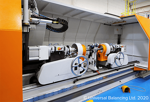
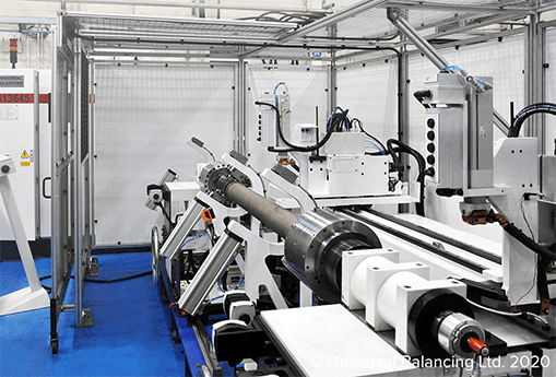
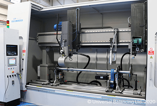
To identify the position and amount of unbalance, balancing machines are used by a rotor manufacture to correct any unbalance that exists. These machines are so sensitive that they can easily and accurately identify any mass axis 0.001mm off the running axis.
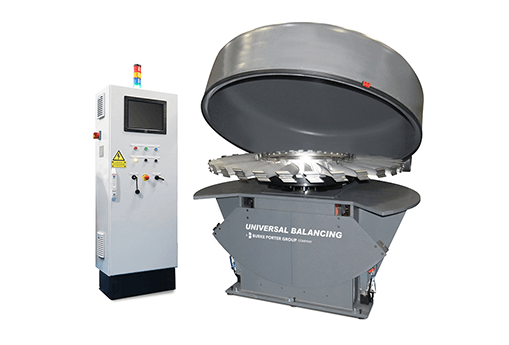
One type of machine will only identify static unbalance. This is used for balancing disk shaped parts. Another type of machine will identify unbalances in two axial planes, e.g. for balancing a rotors whose length is proportionally greater than its diameter. These machines are available in versions that balance the rotor in either the horizontal or vertical axis.
With the use of modern electronics, accuracy easily exceeds national and international standards. The set-up of the machine is very simple by just typing measurements into a computer.
BALANCING RIGID ROTORS
Because unbalance exists in a component even when stationary, rigid rotors can be balanced at a low speed, just enough to produce a centrifugal force to register the unbalance.
BALANCING FLEXIBLE ROTORS
This type of rotor is balanced at a low speed where the rotor does not flex. Correction for unbalance is made, then the speed is gradually increased, and the unbalance is corrected in stages until the rotor’s operating speed is reached.
MODERN TECHNIQUES
With the high cost of replacing damaged rotors, the airline industry stipulates that parts or sections of rotors that are changed must maintain an acceptable balance. The technique involves using dummy adjacent parts, for example balancing a compressor module with a dummy turbine module and replacing compressor and turbine blades without any further balance. These techniques are available to general industry if customers require them.
SUMMARY
The latest production methods reduce or eliminate the need for balancing in low speed applications, but with ever increasing speeds used on rotating machinery, dynamic balancing will be necessary for the foreseeable future. An understanding of dynamic balancing streamlines the complete production process.


